The thermal power plant not only has a complex production process, but also has a wide variety of working media (water, gas, oil, and coal, etc.), and has a variety of shapes. The flow rate measurement principles and methods used for the instantaneous flow measurement of the working fluid are numerous, and the thermal power plant index calculation and consumption Differential analysis and other application systems need to call up the real-time data of the cumulative flow of the working fluid, and objectively require different cumulative flow calculation methods based on the different principles of the flowmeter to be implemented in the unit DCS system.
Based on the analysis of various typical flow measurement applications in thermal power plants, the author proposes an algorithm for calculating the cumulative flow in the unit DCS system, and describes in detail the implementation methods of various flow accumulation algorithms in the TCS-3000 DCS system. It is proved that these algorithms are simple to implement and have high precision, which solves the problem that the DCS system of the unit can accurately calculate the cumulative flow.
1 time interval method
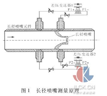
The main feedwater flow measuring element of a boiler in a thermal power plant generally adopts a long-radius nozzle. It uses the ISO5167-1 and GB/T2624-2006 standards for calculation, design, manufacture, and acceptance. The uncertainty of the outflow coefficient is not more than ±1% and it has a measurement accuracy. High, low pressure loss and long life, the measurement principle is shown in Figure 1.


In Figure 2, "MoxGetTime" is the system time function block, which can provide the real-time clock value in the DPU module during continuous program scanning. The "MS" output represents the current millisecond value. The data type is integer and the value range is 0 ~ 999, when the new 1s starts, zero and re-count; "ANY TO REAL" is the data type conversion function block, which can convert the integer to single-precision floating-point number; "TP" is the pulse generator function block, When the operator needs to manually clear the cumulative flow value, click the "Reset" button (reset button associated with the variable MZH10DP101 R). The "TP" function block will generate a pulse width of 1s; the "ST TTL" function block is completed. The cumulative amount of change in traffic over a time interval.
According to Figure 3, the ST TTL functional block implementation principle is as follows:
a. Two consecutive algorithm blocks are called within the same second. Assume that the time when the "ST TTL" function block was called the previous time is t1, the corresponding instantaneous flow rate is q1, the time when the "ST TTL" function block is called again within the same second is t2, and the instantaneous flow rate at this time is q2. Corresponds to the accumulated flow variation ΔQ = q2 × (t2-t1) within the time interval (t2-t1);
b. The time for two consecutive algorithm blocks to be called is not within the same second. Assume that the time when the "ST TTL" function block was called the previous time is t3, the instantaneous flow rate corresponding to this time is q3, and the time when the "ST TTL" function block is called again is t4 (not the same as t3). The instantaneous flow rate is q4, which corresponds to the cumulative flow rate change ΔQ = q4 × (1000 - t3 + t4) during this time interval.

This method of integrating the flow through the instantaneous flow rate to obtain the cumulative flow rate is relatively simple, but it should be noted in practical applications: The acquisition error of the analog input channel has a great influence on the accurate calculation of the accumulated value, especially when the instantaneous flow rate range is relatively low. When large, the influence is greater. Therefore, the analog channel must be calibrated and the error corrected before use. The flow measurement unit is properly selected because it is an incremental operation on the instantaneous flow and the calculation interval is a maximum of 1 s. If the instantaneous flow unit is selected “t/hâ€, the instantaneous flow rate value is much smaller than the value of the “kg/s†measurement unit, and the error is large when the incremental accumulation operation is performed. Therefore, the measurement unit must be properly selected according to the actual situation.
2 pulse frequency method
In order to avoid the acquisition error of the analog input channel in the time interval algorithm, a more effective method is to digitize the instantaneous flow rate. A common method is to express the instantaneous flow rate with a pulse frequency signal. Three turbines are pumped to the industrial extraction flowmeter. The YF100CD vortex flowmeter manufactured by Shanghai Yokogawa Electric Co., Ltd. is used. It is equipped with dedicated signal cables and flow converters. The converter provides pulse signals whose frequency is proportional to the instantaneous flow rate. This signal was introduced into the PM306-2AA pulse frequency input card [2] of the DCS system. The module can measure pulse frequencies in the range of 0 to 600 kHz pulses. According to the YF100CD vortex flowmeter instruction manual, the instantaneous flow rate and flow rate and pulse frequency are shown in Table 1.

Dividing the instantaneous flow pulse frequency value by the flow pulse frequency coefficient to obtain the instantaneous volume flow rate of gas, and dividing the gas specific volume value by the corresponding pressure and temperature to obtain the instantaneous mass flow rate of the gas [3, 4]. Finally, the gas can be obtained by the time interval method. Accumulated flow value.
3 unit mass pulse method
The AT868 Clamp Ultrasonic Flowmeter manufactured by GE Corporation was used to measure the condensate replenishment flow of the unit. The ultrasonic flowmeter of this type has an on-site display meter, which has the functions of instantaneous flow display and cumulative flow calculation. In addition to providing a 4-20mA current signal representing the instantaneous flow rate, the meter also provides "unit quality" pulse function, that is, the flowmeter outputs a pulse each time the total amount of media flowing through the pipe reaches a certain set value. The "unit mass" not only achieves the purpose of calculating the cumulative flow rate but also eliminates the influence of the analog acquisition error on the cumulative flow calculation. The DCS system obtains the cumulative flow through the conversion after obtaining the pulse value of the unit mass through the pulse acquisition card. The algorithm is shown in Figure 4.

In Figure 4, "CI 23 01" is the cumulative pulse value of channel 1 of the pulse acquisition card; "ANY TO REAL" is the data type conversion function block, which can convert integers to single-precision floating-point numbers; "*" is single-precision. Multiplication function block; The constant “0.1†represents the unit mass per pulse (In practical applications, if the “unit mass†pulse frequency is not very high, you can use ordinary DI card instead of pulse acquisition card to collect “unit qualityâ€. Pulse).
4 serial communication method
The heat network supply and return water heat totalizer is used as a trade settlement instrument and requires high precision and systematic errors for each component. The UR-1000 five-channel ultrasonic flowmeter manufactured by Korea Changmin Co., Ltd. was used to measure the instantaneous flow of supply and return water, and the instantaneous flow pulse frequency signal was sent to the heat totalizer, and the supply and return water temperature and pressure compensation signals were connected. Accumulator, through the look-up table program to obtain the corresponding hot water "ç„“" value, multiplied by the instantaneous flow to get the instantaneous heat, and finally integrate the instantaneous heat to get the accumulated heat. The serial communication method can be used to make the DCS system read the parameters such as "instant heat" and "accumulated heat" of the heat calculator. The general heat meter supports the Modbus communication protocol. The TCS-3000 DCS system is configured with a serial communication server to realize the communication between the DCS system and third-party devices. The default communication protocol is the Modbus protocol, and the “baud rate†and “ The communication parameters such as “check bitâ€, “register base address†and “number of registers†are downloaded to the communication server in the form of *.ini configuration file. After the power is turned off and restarted, the serial communication with the heat totalizer can be realized. The configuration is shown in Figure 5.

It should be noted that the "accumulated heat" data in the calorimeter generally uses the IEEE 754 format, with 4 bytes for a single-precision floating-point number, and Modbus-RTU only supports 16-bit data registers, which must be stored in two consecutive registers." Accumulation of heat data. In the TCS-3000 DCS system, when a floating-point variable is associated with a Modbus register in the communication server, the DCS system automatically defaults to assign two Modbus register data to the floating-point variable.
5 Concluding remarks
Accurate calculation of the cumulative flow of the working fluid in the DCS system of the unit is of great significance for the calculation of the thermal power plant index and the analysis of the consumption difference. The four “accumulated flow†calculation methods described by the author are already in the 2×330MW project of the Xinjiang Urumqi Thermal Power Plant of Huadian. The application in practice shows that the implementation is simple and the precision is high, which solves the problem that the DCS system of the unit accurately calculates the cumulative flow of the working medium.
references
[1] GB/T2624. 3-2006, Measurement of full-pipe fluid flow using a differential pressure device installed in a circular cross-section pipe [S]. Beijing: China Standard Press, 2006.
[2] Li Yu, Zhang Xiaoyan. The theoretical study of pulse signals measured by DI module and its application examples [J]. Automation Instrumentation, 2002, 28( 10): 65 ~ 67.
[3] Xia Bing. Application of PLC in flow display and cumulative measurement [J]. Metrology Technology, 2009, (10): 37 ~ 38.
[4] Dong Qinglong, Hu Jiwei. The realization of flow accumulation function in PLC system [J]. Refining and Chemical Industry, 2007, 18( 3): 50 ~ 51.
Spandex Warping Machine
Spandex warping machine also called spandex yarn warping machine; elastic yarn warping machine.
A-ZEN spandex warping machine AZE318 with vertical creel is driven by 5 sets high performance servo motors and adopted with advanced precisive laser to measure distance so that spandex warping is more stable, well equipped with and easier to operate. It is suitable for warping all kinds of spandex, especially for requirement of knitting high quality elastic textiles.
Technical Data:
Warp Line Speed: 100-600m/min;
Beam Size: Φ21"*21";
Warping ends: According to customers` demand;
Pre-drafting: 0-200%; Final Draft: 15-100%;
Brake time less than 0.6 s, the deviation of stop synchronization is less than 3%;
Creel Capacity: 616, 700, 728, 784, 792, 896, etc.
Servo Motor Power: Warper head power 13.2KW, Warper Head Tension Roller 2.9KW, Draft Roller 4.6KW, Creel: 2*6.9KW;
Main Motor: 10KW AC frequency conversion control;
Control Mode: Computerized real-time control, and user-friendly operation interface.
Spandex Warping Machine,Elastic,Beam Warping Machine, Yarn, Computerized Split Yarn Warping Machine
CHANGZHOU A-ZEN TEXTILE TECHNOLOGY CO.,LTD , https://www.tricotmachinery.com